Handheld 3D Scanner for CNC Routers and Reverse Engineering
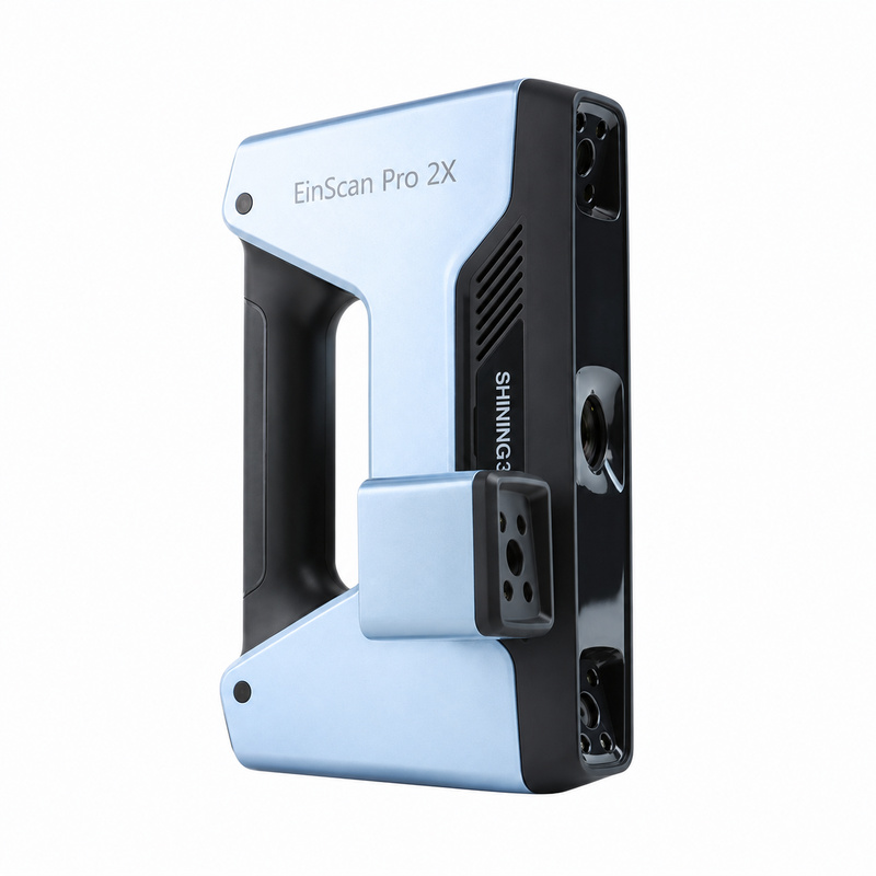
Turn existing shapes into digital references for your next manufacturing project. A handheld 3D scanner captures accessible object surfaces and creates data that can be processed into a three-dimensional model.
For furniture manufacturers, carving workshops and product designers, scanning provides a practical starting point when an original object exists but suitable digital drawings are unavailable.
Scanning is the first stage of the workflow. Model cleanup, CAD preparation where required, and CAM programming are still needed before CNC machining.
From Physical Objects to Digital Models
Complex curves, sculpted details and irregular surfaces can be difficult to describe with manual measurements alone. Handheld scanning allows an operator to capture the object from different viewpoints and combine the captured surfaces in scanning software.
The resulting model can serve as a reference for reproduction, modification, digital archiving or further design work.
Capture quality depends on surface visibility, material, tracking, calibration and operator technique. Recesses and hidden areas may require additional viewpoints or separate measurement.
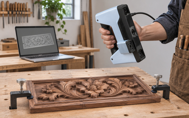
Wood Furniture and Decorative Relief Digitization
A handheld 3D scanner can support the digitization of carved furniture details, ornamental panels, decorative moldings and other shaped components.
A scanned reference gives designers a basis for adjusting proportions, rebuilding damaged features or preparing a related design for CNC carving.
Typical applications include:
Carved furniture ornaments: capturing floral patterns and decorative surfaces.
Relief panels: recording raised details for model preparation.
Custom furniture components: collecting shape references for redesign.
Replacement details: documenting an available original before developing a matching component.
The reproduction result also depends on the CNC machine, cutter diameter, material and toolpath strategy. Fine scanned details may need adjustment to suit the machining process.
Sculpture and Stone-Carving Model Capture
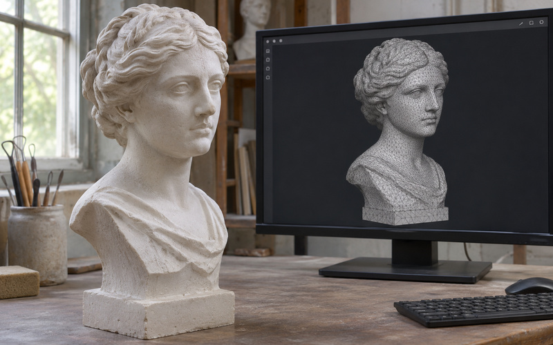
Sculptures, busts and decorative art objects can be digitized as references for digital sculpting and carving preparation.
The model can be inspected, resized or refined in compatible software before a manufacturing workflow is selected. This can help workshops develop carving projects from physical originals.
A scanner records the visible surface; it does not reveal internal geometry. Undercuts and deep recesses may also be difficult to capture or machine. Assess both scanning access and cutter access before planning reproduction.
Reverse Engineering and CAD Preparation
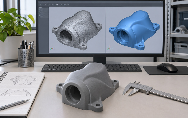
For product development, scanning provides surface information from an existing sample. Designers can use the processed data as a reference when rebuilding shapes or developing a revised component.
A scan mesh and an editable CAD solid are different types of data. Creating engineering surfaces, dimensions and design features may require separate reverse engineering software and manual modeling.
Functional dimensions, mating surfaces and tolerances should be checked with methods appropriate to the project. Do not assume that a visually complete scan is sufficient for precision part acceptance.
A Practical Scan-to-CNC Workflow
Prepare the object. Stabilize it and assess surface finish, accessibility and lighting.
Set up the scanner. Follow the calibration and tracking requirements for the supplied model.
Capture overlapping views. Move steadily and collect the accessible surfaces from suitable angles.
Process the scan. Align and merge views, remove unwanted background data and review missing areas.
Prepare the model. Verify scale and orientation, then clean the mesh or reconstruct CAD geometry as required.
Create CAM toolpaths. Choose the stock, cutters, machining strategy and machine-specific postprocessor.
Verify before cutting. Simulate the toolpaths and check setup, clearance and machining limits.
Scan data is not ready-to-run CNC code. Successful production requires a verified model and an appropriate machining program.
Mesh Export and Software Compatibility
Common mesh formats used in scanning workflows include STL, OBJ and PLY. Confirm the export options available in the supplied scanner software and the import capabilities of your design or CAM software.
For CNC carving, the geometry is usually the main requirement. Capturing color texture is a separate capability and may require an optional camera or accessory package.
Confirm software licenses, accessory requirements and computer specifications before ordering.
Surface Preparation and Scanning Conditions
Matte, opaque surfaces are generally easier to capture than transparent or highly reflective objects.
Depending on the object and scanner configuration, preparation may include suitable tracking markers or an approved scanning spray. Check surface compatibility before applying any treatment, especially to valuable or delicate originals.
Use controlled indoor lighting and follow the operating instructions for the supplied model.
Frequently Asked Questions
Can the scanner connect directly to a CNC router and start cutting?
The scan must first be processed into a suitable model. CAM software then creates toolpaths and machine-specific output for the CNC controller.
Can scanned furniture details be resized?
Yes. A processed model can be scaled in compatible software. Check the resulting detail size, cutter access and material thickness before machining.
Does the scanner automatically create an editable CAD model?
Scanning normally produces surface or mesh data. Editable engineering geometry may require additional reconstruction in suitable CAD or reverse engineering software.
Can it scan reflective or transparent objects?
These surfaces can be challenging. Suitable preparation may be necessary, and the intended object should be evaluated before purchase.
What information should I provide before ordering?
Provide the object dimensions, material, surface finish, smallest detail to capture, required accuracy and intended use. Also identify your CAD/CAM software and computer configuration so the appropriate scanner package can be confirmed.


 English



